Explore the world of Concorde with Heritage Concorde
Concorde Engine Air In-take System
There was only one engine that was suitable and available for Concorde at the start of its development of the aircraft, it was the Rolls-Royce Olympus, but although suitable for further development for Concorde, no jet engine can accept air in its compressors at supersonic speeds, which is of course required for a supersonic Mach 2 airliner.
It was therefore necessary for the engineers to slow the air down from Mach 2 to Mach 0.5 (which is about 1,350 mph to about 500 mph) at which point it is at a suitable speed at which to enter the engines. So the engineers had to come up with an answer to how they could slow the air down, the answer was the eleven foot in length air in-takes. The air in-take is best described as a self-starting in-take system. What does this mean, well the engines do not lock into a surge necessitating engine shut down.
The Air Intake Control System satisfies the basic requirements to supply the correct amount of air at a high efficiency and in a form that is acceptable to the engines at all flight and engine operating conditions of the aircraft. Experience on the prototype Concordes brought about a bold change from analogue to digital control late in the development programme, this decision was initially, vehemently opposed by the French, but in the end the right decision was arrived at and fitted to the aircraft.
The air-intake assemblies are the most critical part of the whole powerplant, assuming that they are operating correctly, with all the shockwaves in the correct positions, they produce 63% of the net positive thrust of the powerplant. The incredible intake design allows Concorde to do something that no other aircraft has ever been able to do to date, which is cruise at Mach 2 and above without the continued use of the powerplant reheats.


Concorde has many interesting technical features, but its variable geometry engine air in-take system has to stand out as one of the most outstanding ones. Its function is required to ensure that the Olympus engines get just the right amount of air moving at the correct speed through a wide variety of airspeeds. The air in-take is rectangular in cross section and is of variable geometry in that it embodies two moving ramps in the top surface, the ramps forward and aft, which do not meet, but move up and down to control airflow. The in-takes also have two smaller doors which either let in more air or spill it when not required by the engines. The moving parts of the air in-takes are operated hydraulically under computer control; this was found to be necessary during the prototype development stages.
Although to the naked eye all the in-takes look the same at first, they are in fact toed-in along the incident lines of entry flows. During the aircrafts supersonic speeds this has the effect of producing the optimum entry conditions, but during the aircrafts take-off with all four engines rotating in the same direction, the effect on the blade vibrator modes is markedly different between engines. So much so that N1 (Engine speed relationship) engine 4 is automatically held down up to 60k, when it is released.
Once the Concorde is above Mach 1.3 the ramps and spill doors are positioned between scheduled maximum and minimum angles which are determined by the intake pressure ratio, Mach numbers, and engine speed N1, angle of attack and actual ramp/spill door positions. Changes in ramp angle alter the in-take of air and create a shockwave system that originates at the ramp angle and which converges on the lower lip of the intake when optimum configuration of the ramp is reached. Consequently, this is an external compression system and it is this shockwave system that slows down the air entering the in-take to Mach 0.5, which is all so important for the engines. Once the scheduled ramp angle is reached in the in takes, the excess air is dumped through the spill doors, see pictures for details of this procedure.
A.- TAKE-OFF
(See diagram 1& 2)
During this time the engines require the maximum airflow
All the secondary air doors are closed which means that the engine bay is isolated from the intake airflow; this causes all the intake air to flow into the engine. The ramps are now fully up, the auxiliary inlet vane (which is part of the spill door assembly) is wide open and held open aerodynamically, this allows extra airflow into the engine.
Once at Mach 0.93 the auxiliary inlet is closed, and than above Mach 1.3 the in-take ramps then come into play, by lowering to form a series of shock waves which starts from the bottom lip of the air intake, which is machined to a fine Sharp point. This now has the effect of slowing the air down. Once Concorde has reached mach 2, the ramps would have moved over half their possible travel distance

B. – Noise abatement
(See diagram 2)
Once Concorde has taken off, it enters a period of flight known as the noise abatement procedure, this see’s the afterburners turned off and power reduced. The secondary nozzles remain in their take-off position when the engines are throttled for noise abatement.
As the aircraft accelerates the angle reduces such that by M=1.1 the secondary nozzles are fully open forming the divergent part of the back of the power plant.
Hence the name of the procedure “noise abatement”
The Secondary air doors would also be open at this stage of flight, and this allows the air to bypass the engine (see the diagram). While Concorde is travelling at slow speeds all the air and which is required goes into her engines and is known as primary airflow, this means that they would keep the secondary doors closed during this time. This also stops the engine from ingesting any of its own exhaust gases

DIAGRAM 2
DIAGRAM 1
C. – Supersonic Cruise
(See diagram 2)
During Mach 2 flight, the air is not only slowed down by the in-takes, it is also compressed and considerably raised in temperature. This compression at this stage of flight is helpful because it means that the engines own compressors have less work to do, but the rise in temperature of about 200C leads to the necessity for special metals in the engine, for further details see the section relating to the Olympus 593 powerplant.
While Concorde is in flight, it meets all the changes with air temperature and pressure which causes disturbances to the wave pattern in the in-takes. The computers can sense these changes during the flight and make any final necessary adjustments to the ramp positions in the in-takes, which maintain the airflow required by Concorde’s four engines. Equally, any changes in engine power settings require some changes in the airflow; Concorde’s computers can deal with this in the same way.
Each in-take, then, presents high-pressure hot air at Mach 0.5 to the first stage of the Olympus 593 mk610 engines, and in doing do the in-takes have done their job.
D. – Reverse Thrust
(See diagram 2)
Once the aircraft has landed, the secondary air doors, auxiliary inlet vane along with the ground running flap will all be in their open position.
ENGINE FAILURE
If this happens to Concorde during supersonic speeds, it could theoretically caused a catastrophic failure of the airframe altogether.
The most difficult case of change in demand would be if an engine was to fail during the flight, or shut-down at high speed. Suddenly, the engine would require little or no air. So the ramps would go down fully, diverting some air over the top of the engine, while the spill door would open wide to pour air out of the underside. The speed of this operation would obviously be critical. Concorde’s ability to deal with sort of problem is most impressive slam-closure of a throttle at Mach 2 makes Concorde react, but the engine doesn’t even hiccup.
This need suddenly to dump air produces the one odd flying characteristic of the aircraft, if an engine fails at supersonic speed, Concorde banks the wrong way. Any aircraft, Concorde included, will yaw towards the dead engine; thrust on that side has suddenly been lost, and the engine has become a producer of drag. As a result, the wing on the side opposite to the failed engine will temporarily move faster, gain lift and rise.
The combined effect is both roll and yaw towards the dead engine. But at Mach 2 there is all the excess air to get rid of. This spill door opens and the in-take air is deflected downward. This causes the wing to rise and Concorde to bank away from the dead engine. The technique for dealing with this situation is first to level the wings, then to counter the yaw with the rudder. The auto-stabilizers will already have applied some rudder so it is not a difficult process for the pilot.


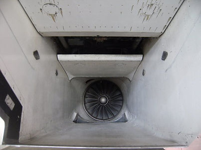
This picture shows the auxiliary intel vane vide open